
40m
40 m drone demonstration
Power delivery to a drone over a 40 m link, with 20 W electrical output and a 15 g optical receiver.
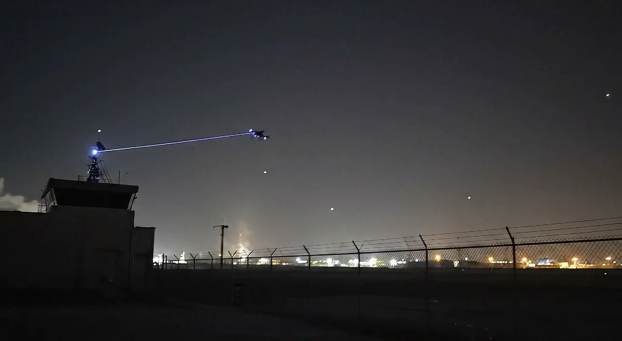
Laser power beaming
Laser power delivered in flight. Demonstrated over 40 m to a drone and 1.5 km to a fixed receiver.
Prototype systems for integration and pilot evaluation.
Measured in separate test configurations
40m
Power delivery to a drone over a 40 m link, with 20 W electrical output and a 15 g optical receiver.
1.5km
A 1.5 km roof-to-roof link with a stationary receiver, studied across varied weather conditions.
Programs and support




The operational problem
In a single-aircraft operation, landing to replace a battery interrupts aerial coverage. Overlapping flights can maintain coverage, but require additional aircraft and coordination.
The aircraft leaves its position while the mission continues without its aerial view.
Operators manage landing cycles, replacement batteries and relaunch alongside the mission.
How it works
A controlled ground-to-air link connects the transmitter, tracking system and onboard receiver. Integration and operating conditions are evaluated for each mission.
Electrical source
On the ground
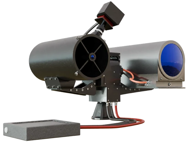
Ground transmitter
Tracking and beam control
Optical power channel
Line of sight
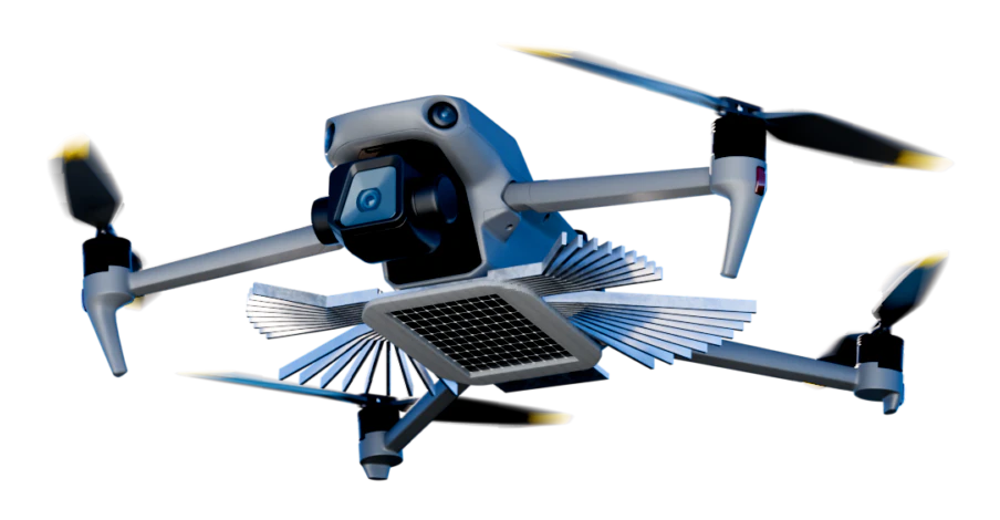
Onboard receiver
Power to the aircraft electrical load
The ground unit converts electrical input into directed optical power.
Ground-based tracking keeps the optical link aligned with the airborne receiver.
The onboard receiver converts incoming light into usable electrical power.
Application concepts
01
Aerial observation for perimeter and asset protection.
02
Inspection and monitoring around industrial assets and infrastructure.
03
Power delivery to fixed equipment where cabling or battery service is difficult.
In-flight power, remote operations and mobile coverage, brought together in one short visualisation.
Visualisations of optical power delivery to a drone in flight, remote equipment and a drone supporting a moving convoy. Music only; no spoken dialogue. A text description of each scene is available in the Applications page's scene descriptions.
Choosing an energy approach
External power through a physical cable.
Compare cable constraints with the aircraft movement your mission requires.
Recharging on the ground.
Check whether landing cycles fit the required coverage.
Power restored through a battery change.
Check staffing, logistics and any handover between aircraft.
Energy delivered to a compatible receiver without a physical cable.
Evaluate line of sight, operating geometry, receiver integration and site-specific safety requirements.
Future applications
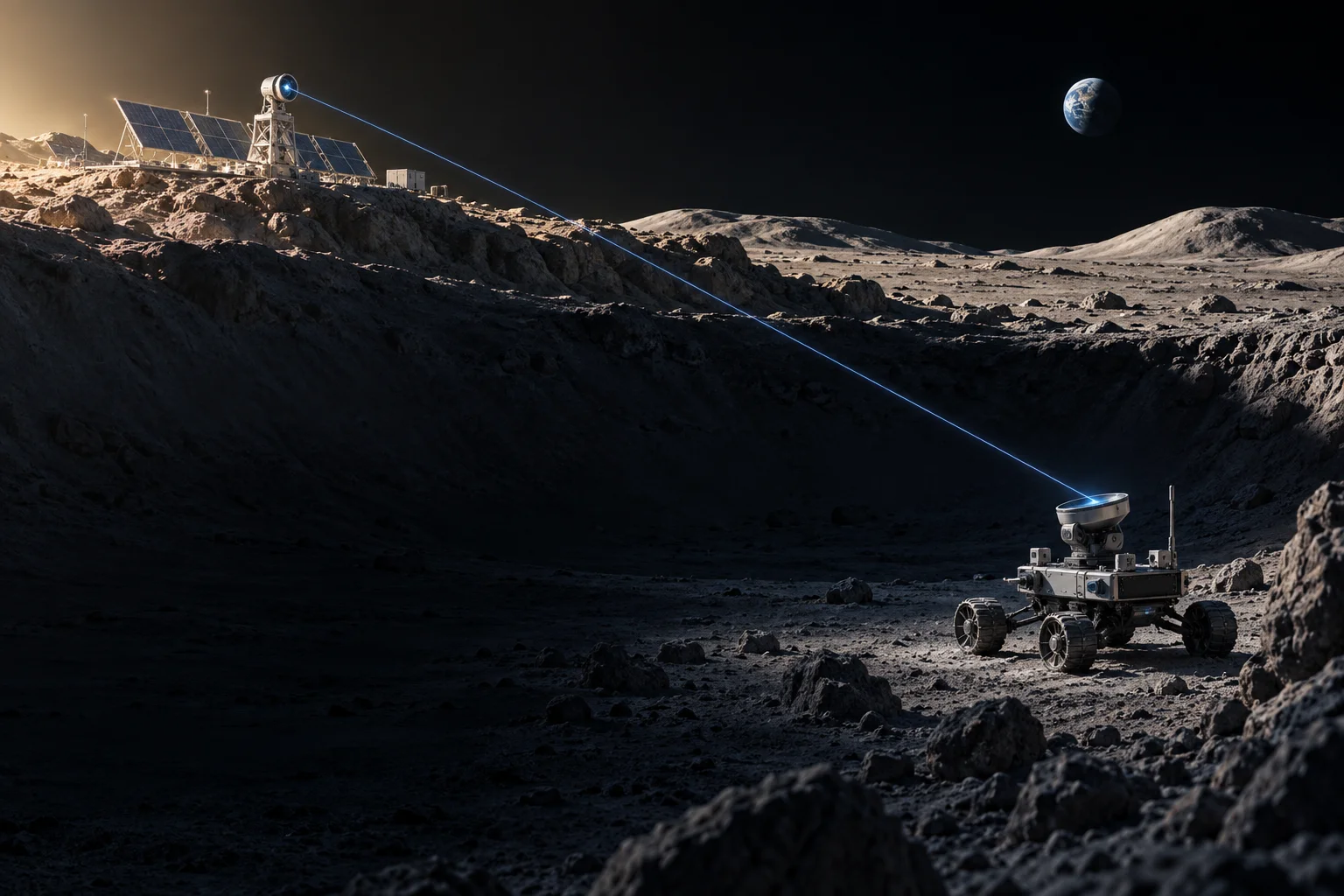
Our longer-term research explores power delivery between spacecraft and to lunar assets beyond sunlight. The next questions are optical capture, pointing, thermal management and system mass.
Collaboration
Tell us about your platform, operating site and the task you need to keep running. Technical details are useful when available, but are not required to start the conversation.
Define the aircraft interface, power needs and operating geometry.
Review receiver mounting, electrical interfaces and control states.
Agree operating conditions, interlocks and the measurements required.