
Technology
How laser power reaches the aircraft
Power generation, tracking and beam control remain on the ground. A compatible airborne receiver converts the optical link into usable electrical power on the aircraft.
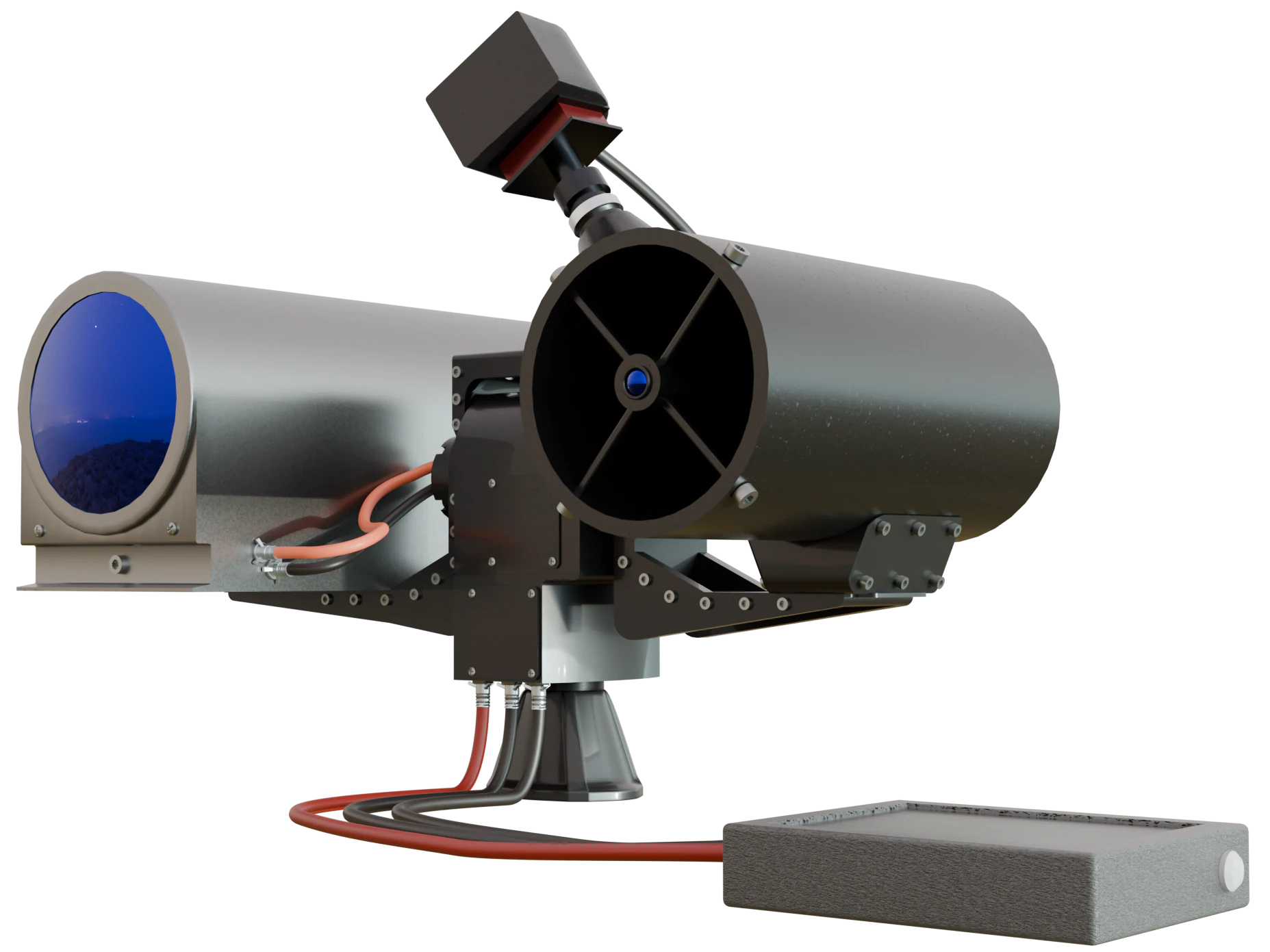
System architecture
Three layers, one controlled link.
Layer 01
Ground optical unit
Generates and directs the optical energy link from a controlled site.
Layer 02
Tracking and control
Maintains alignment and monitors the conditions required for transmission.
Layer 03
Airborne receiver
Converts incoming optical energy and interfaces with the aircraft power system.
Performance in context
Demonstrated results
| Parameter | Demonstrated |
|---|---|
| Drone link distance | 40 m - airborne receiver |
| Fixed-receiver link distance | 1.5 km - stationary receiver |
Results refer to the linked test configurations.
Design targets
Engineering the next stage
Project goals for higher-power systems, separate from the demonstrations above. Targets depend on the selected configuration and are not a single guaranteed operating point.
- Electrical output
- 1–3kW
- Target power delivered at the receiver.
- Line-of-sight range
- 1–5km
- A clear optical path and a compatible receiver are required.
- DC-to-DC efficiency
- 10–20%
- Electrical input to electrical output, a different boundary from receiver conversion.
- Light-to-electricity efficiency
- 30–40%
- Optical-to-electrical conversion at the receiver.
- Failsafe response
- <10ms
- Protective-response target; trigger and timing boundary require validation.
- Tracking precision
- <0.01°
- Angular precision target, to be verified under defined operating conditions.
- Output-to-mass target
- 1 kW/ 600 g
- Electrical output. The hardware included in the mass budget must be defined for the configuration.
- Custom battery charging
- 80%in ≤5 min
- Target for a compatible custom battery, with capacity, initial charge and charge profile specified.
- Externally powered endurance
- Externalsupply
- Operation can continue while ground power and a usable optical link are maintained. Backup energy must be sized for interruptions.
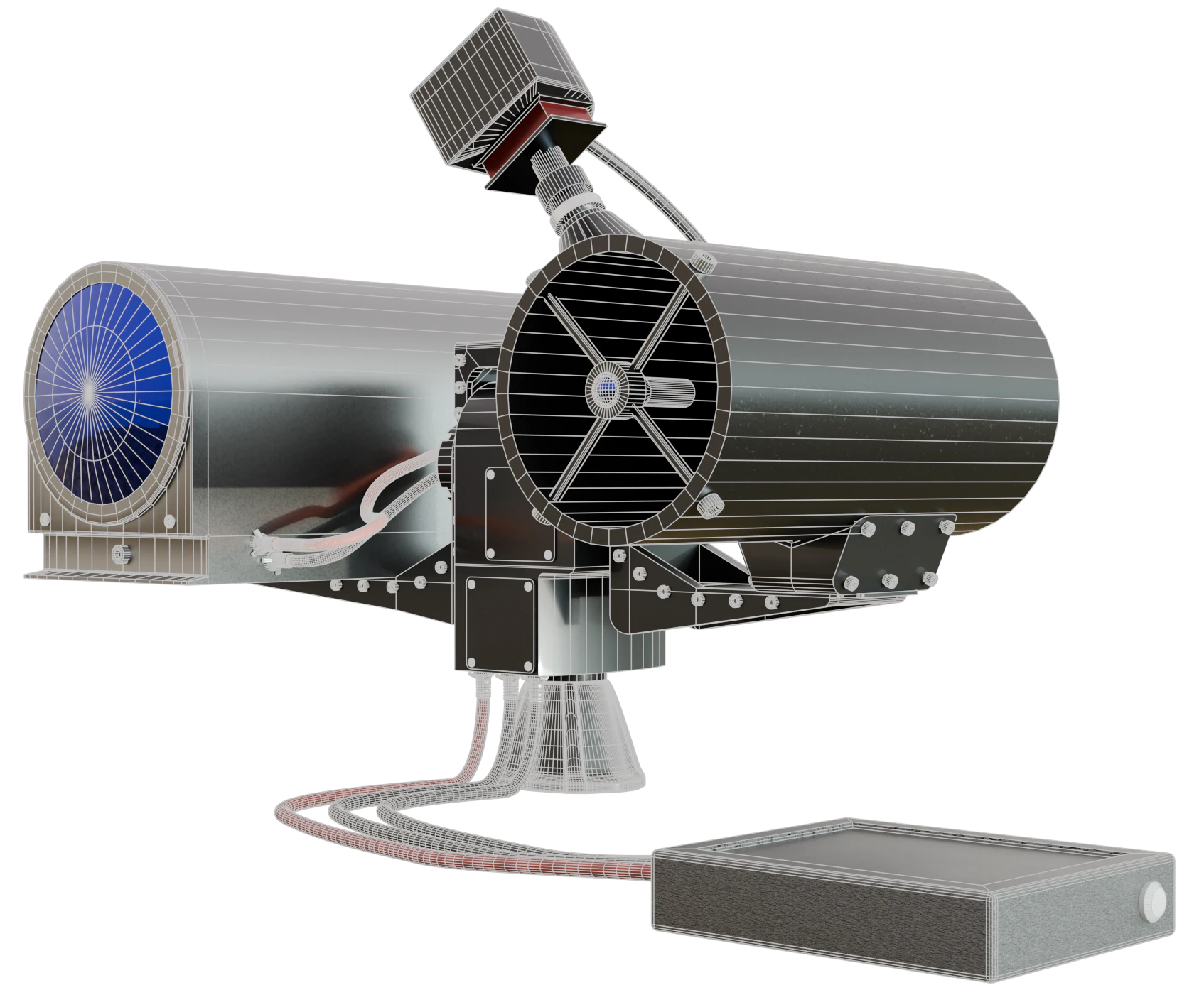
Ground unit
Ground transmitter
The ground unit brings optical transmission and tracking interfaces into a transportable architecture. Site geometry, power supply and operating controls are defined for each validation setup.
- Transportable system architecture
- Mission-specific site setup
- Defined operating and shutdown conditions
Airborne receiver
Onboard receiver
The receiver is not a universal add-on. Its optical aperture, electrical interface, thermal behavior and mechanical integration must fit the selected platform and mission.
Electrical fit
Voltage, power demand and aircraft power architecture.
Mechanical fit
Mass, mounting, field of view and payload interaction.
Control fit
Interlocks, telemetry and validated operating logic.
Optional data
Configuration-specific optical communication channel.

Integration requirements
Define the power link around your aircraft.
A useful specification starts with the energy the aircraft needs and the route the beam must follow. These are the inputs and measurements we review together.
Operating geometry
Ground-to-air distance, altitude, field of view and expected aircraft movement.
Electrical power
Aircraft bus voltage, hover demand, payload load and required onboard reserve.
Tracking and interruption
Acquisition, motion envelope, loss of alignment and recovery behavior.
Receiver integration
Available mass, mounting position, optical aperture and thermal limits.
Optional optical data
Required data flow and interfaces, evaluated separately from the energy budget.
Site and visibility
Obstructions, weather, access control and launch/recovery area.
Ground energy budget
Available electrical supply, supply type, cooling, operating duty and reserve.
Power flow and backup
Supplying the aircraft load, charging a battery from surplus power, and operating from onboard reserve when the beam is absent.
Power at the site
Ground power requirements
Delivered power is only one part of the energy budget. The electrical input must cover conversion losses and the equipment used to maintain the link.
Input power = delivered power ÷ DC-to-DC efficiency
The integration review defines the measurement boundary: whether cooling, tracking, control electronics and AC/DC conversion are included. Site supply is sized from that complete budget, the operating duty and the required reserve.
Supplying the aircraft load and charging its battery are different operating modes. Battery charging needs net available power after the load and conversion losses.
The operating environment
Operating limits
Line of sight
The transmitter and receiver need a clear optical path within the defined operating geometry.
Weather and visibility
Dense fog can interrupt the link. Rain, snow, haze and turbulence affect delivered power and operating availability.
Receiver integration
Electrical, mechanical and thermal integration must match the platform and its mission.
Site control and backup power
The operating area, laser safety measures and response to loss of the power link must be defined before a pilot.
Ground power
The transmitter requires an electrical supply sized for delivered power, conversion losses and auxiliary equipment.
Choosing an energy approach
Compare the energy approaches.
Tethers, charging pads, battery swaps and laser power beaming solve different operating problems. Compare the integration requirements against your aircraft, mission and site.
Expand a criterion to compare all four approaches.
Movement while externally powered
- Tethered power
- Limited by tether geometry.
- Landing / charging pad
- The aircraft is on the pad.
- Battery swaps
- No external supply during the swap; onboard energy between swaps.
- Laser power beaming
- Within the evaluated optical path and tracking envelope.
Landing for replenishment
- Tethered power
- Not required while operating on the tether.
- Landing / charging pad
- Required.
- Battery swaps
- Required for conventional landed swaps.
- Laser power beaming
- Not required while receiving power in flight. Battery charging depends on net available power.
Working distance
- Tethered power
- Cable and system dependent.
- Landing / charging pad
- The aircraft must return to the pad.
- Battery swaps
- Mission and battery dependent.
- Laser power beaming
- Demonstrated distances and development targets must be considered separately.
Deployment
- Tethered power
- Site and equipment dependent.
- Landing / charging pad
- Pad location, approach and electrical supply.
- Battery swaps
- Battery stock and handling workflow.
- Laser power beaming
- Transmitter, supply, alignment and a controlled operating area.
Onboard mass
- Tethered power
- Aircraft-side equipment and tether load.
- Landing / charging pad
- Battery and platform-specific interface.
- Battery swaps
- Battery and any swap interface.
- Laser power beaming
- Receiver, conditioning, mounting, thermal hardware and reserve battery as applicable.
Weather
- Tethered power
- Aircraft and tether operating envelope.
- Landing / charging pad
- Aircraft, landing and pad envelope.
- Battery swaps
- Aircraft and handling conditions.
- Laser power beaming
- Aircraft envelope plus optical-channel visibility.
Safety planning
- Tethered power
- Aircraft, cable and electrical risks.
- Landing / charging pad
- Aircraft, landing and battery/charging risks.
- Battery swaps
- Aircraft and battery handling.
- Laser power beaming
- Aircraft and electrical risks, plus laser exposure, reflections and site/airspace control.
| Criterion | Tethered power | Landing / charging pad | Battery swaps | Laser power beaming |
|---|---|---|---|---|
| Movement while externally powered | Limited by tether geometry. | The aircraft is on the pad. | No external supply during the swap; onboard energy between swaps. | Within the evaluated optical path and tracking envelope. |
| Landing for replenishment | Not required while operating on the tether. | Required. | Required for conventional landed swaps. | Not required while receiving power in flight. Battery charging depends on net available power. |
| Working distance | Cable and system dependent. | The aircraft must return to the pad. | Mission and battery dependent. | Demonstrated distances and development targets must be considered separately. |
| Deployment | Site and equipment dependent. | Pad location, approach and electrical supply. | Battery stock and handling workflow. | Transmitter, supply, alignment and a controlled operating area. |
| Onboard mass | Aircraft-side equipment and tether load. | Battery and platform-specific interface. | Battery and any swap interface. | Receiver, conditioning, mounting, thermal hardware and reserve battery as applicable. |
| Weather | Aircraft and tether operating envelope. | Aircraft, landing and pad envelope. | Aircraft and handling conditions. | Aircraft envelope plus optical-channel visibility. |
| Safety planning | Aircraft, cable and electrical risks. | Aircraft, landing and battery/charging risks. | Aircraft and battery handling. | Aircraft and electrical risks, plus laser exposure, reflections and site/airspace control. |
A framework for integration discussions, not a comparative test of specific products. Suitability depends on the aircraft, mission and operating site.
Safety and integration
Validate the complete operating system.
A useful pilot includes more than optical output. It defines the aircraft interface, tracking conditions, operating area, control states, interlocks and the evidence required to move forward.
Architecture review
Bench integration
Controlled site validation